Draw a line down the middle of most production web apps and you’ll find the same three boxes: something that renders the page, something that runs the logic, and something that stores the data. That split is the 3-tier web application architecture on AWS, and despite a decade of serverless and container hype, it’s still the layout a huge share of real systems ship on.
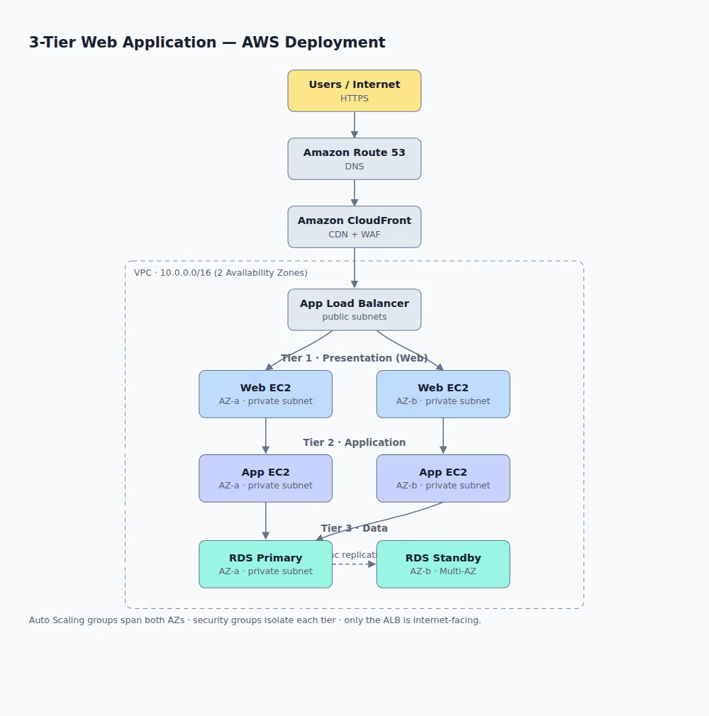
This post isn’t a build-it tutorial. There are fifty of those. It’s a read-the-diagram walkthrough for engineers sizing up the pattern: what each box does, why the network is drawn the way it is, and where this particular reference stops short of production. The diagram below is the whole architecture on one screen, so keep it open as you read.
What “3-tier” actually means (and why it still holds up)
Three tiers, three jobs. The presentation tier handles the UI and static rendering. The application tier holds the business logic. The data tier stores state. Each one runs on its own machines, scales on its own schedule, and gets deployed without dragging the others along.
People keep predicting its death. It keeps not dying. The reason is boring and good: the boundaries are real seams. You can throw more web servers at a traffic spike without touching the database. You can rewrite the logic tier without redrawing the front end. And the database never has a public IP, so an attack on the UI doesn’t reach your data in one hop. That last point is the whole security story, and it’s why the pattern still shows up in fresh AWS reference builds in 2026.
The request path, top to bottom
Follow one HTTPS request through the stack. Every arrow in the diagram is a real network hop with a real reason.
- Amazon Route 53 answers the DNS query and points the browser at the edge.
- Amazon CloudFront takes the request at a nearby edge location, serves cached assets on the spot, and screens traffic through AWS WAF before anything touches your infrastructure.
- Application Load Balancer (ALB) is the front door. It sits in public subnets and it’s the only component with a route to the internet. It spreads requests across the web tier.
- Web tier (Web EC2) renders the UI and hands dynamic calls inward.
- App tier (App EC2) runs the business logic. Nothing on the internet can reach it directly.
- Data tier (Amazon RDS) is the primary database, with a standby replica waiting in a second Availability Zone.
Notice what doesn’t happen: at no point does a user’s request land on a machine that holds your data. Traffic gets handed down, tier to tier, and each handoff crosses a security boundary.
The AWS services mapped to each tier
The tiers are a concept. Here’s the concrete AWS wiring the diagram uses.
Edge and routing
Route 53 for DNS, CloudFront as the CDN, AWS WAF bolted onto CloudFront for Layer 7 filtering. CloudFront caches at 750+ points of presence, and data transfer from AWS origins into CloudFront costs nothing, so you’re offloading origin traffic for free while cutting latency. WAF blocks the usual suspects at the edge: SQL injection, cross-site scripting, bad bots.
Presentation and application tiers
Both run on Amazon EC2, one instance per Availability Zone, inside Auto Scaling groups. The AWS three-tier workshop runs Nginx serving a React front end on the web tier and Node.js on the app tier, but the pattern doesn’t care about your stack. Swap in whatever you run.
Data tier
Amazon RDS in a Multi-AZ deployment: a primary instance in AZ-a and a synchronously replicated standby in AZ-b. The standby isn’t a read replica you query. It’s a warm spare that exists to take over.
Networking and security: the part that earns the design
Everything lives in one VPC on 10.0.0.0/16 spanning two Availability Zones. The interesting decisions are about which subnet each thing sits in.
Only the ALB gets public subnets. The web tier, app tier, and both database instances live in private subnets with no direct route to the internet. If you want the ALB to serve EC2 instances that sit in private subnets, you put the load balancer in public subnets in the same AZs and let VPC routing carry traffic inward. That’s the documented AWS pattern, not a hack.
Then the security groups do the real isolation work, and this is where a lot of teams get lazy. Don’t open a tier to a CIDR range. Open it to the tier above it. Set the ALB’s security group as the source in the web tier’s ingress rule. Set the web tier’s security group as the source for the app tier. Set the app tier’s as the source for RDS. Each layer accepts traffic from exactly one place: the layer directly above it. AWS calls this out explicitly for load balancer targets, and the same logic chains all the way down.
The payoff is defense in depth. A foothold on a web server doesn’t hand an attacker the database, because the database’s security group has never heard of that web server’s IP. It only trusts the app tier.
High availability and scaling
Two Availability Zones is the backbone of the HA story. Each tier has an instance in AZ-a and AZ-b, and the Auto Scaling groups span both. Lose an entire AZ and the stack keeps serving from the other one, at reduced capacity until scaling catches up.
Scaling is per-tier, which is the quiet superpower here. Your app tier is CPU-bound under load but the web tier is fine? Scale the app tier alone. Each layer has its own Auto Scaling group and its own triggers.
The database gets its own resilience mechanism. With RDS Multi-AZ, updates are synchronously replicated to the standby, so a committed transaction is on both instances before the write is acknowledged: zero data loss on failover. When the primary dies, RDS promotes the standby automatically, no manual step. AWS puts a single-standby failover at as quickly as 60 seconds, and the newer Multi-AZ DB cluster (two readable standbys) at typically under 35 seconds. Failover fires on loss of the AZ, loss of network to the primary, or a compute or storage failure. You don’t get paged to run a runbook; you get an event after it already happened.
One design call worth defending: keep the web tier private
Here’s where this diagram breaks from the most-copied tutorial. The official AWS three-tier workshop puts the web tier in public subnets. This reference puts it in private subnets, behind a public-only ALB.
I’d default to private every time. There’s no reason for a web server to hold a public IP when an ALB already terminates the connection and forwards inward. Making the ALB the single internet-facing surface shrinks your attack surface to one well-understood, AWS-managed component. The cost is that private instances need a NAT Gateway for outbound traffic (pulling packages, hitting external APIs), which the public-web-tier layout gets for free. That’s a real bill and a real dependency. Pay it. A smaller attack surface is worth a NAT Gateway.
What this reference leaves out
Be honest about scope. This diagram is a clean skeleton, not a production system. Before you ship, you’ll want at least these:
- NAT Gateway — outbound internet for the private tiers. Effectively mandatory the moment your instances need to reach anything outside the VPC.
- Amazon ElastiCache — a Redis or Memcached layer between app and database to absorb read load and cut latency on hot queries.
- Amazon S3 — park static assets and user uploads in a bucket behind CloudFront instead of serving them off EC2 disks.
- Bastion host or AWS Systems Manager (SSM) — admin access to private instances without SSH keys or exposed ports. SSM Session Manager is the cleaner option; there’s nothing to leave open.
None of these change the three-tier shape. They’re the padding between a diagram and a system that survives contact with real traffic.
Frequently asked questions
Is 3-tier architecture still relevant with serverless and containers?
Yes. The tiers describe how you separate responsibilities, not what you run them on. You can implement the same three-tier split with Lambda, Fargate, or EC2. The pattern outlives the compute fashion of the year.
Why is only the load balancer in a public subnet?
To keep the internet-facing attack surface as small as possible. The ALB terminates public connections and forwards traffic inward, so the web, app, and data tiers never need a public IP. Fewer public entry points means fewer things to defend.
How fast does RDS Multi-AZ recover from a failure?
AWS lists a single-standby Multi-AZ instance failing over in as quickly as 60 seconds, and a Multi-AZ DB cluster in typically under 35 seconds, both with zero data loss and no manual intervention.
What’s the difference between Multi-AZ and a read replica?
Multi-AZ is for availability: the standby is a passive warm spare you don’t query, kept in sync for automatic failover. A read replica is for scaling reads: it’s a queryable copy, replicated asynchronously, and it doesn’t promise the same failover guarantees.
The takeaway
The 3-tier web application architecture on AWS earns its longevity by drawing hard lines: one public entry point, tier-to-tier security groups, independent scaling, and a database that fails over on its own. Start from this skeleton, add NAT, caching, S3, and SSM as you need them, and keep the web tier private. If you’re standing up a reference deployment, this is a defensible place to begin.
Building out your AWS architecture and want a second opinion on the network design? Sketch your tiers, map the security groups tier-to-tier, and pressure-test where your single points of failure hide before you write a line of Terraform.